
Thread whirling is a machining method in which a high-speed rotating thread whirling ring insert fitted with carbide inserts rapidly cuts threads from cylindrical workpieces. The thread whirling ring has a predetermined diameter of the cutting circle calculated on the basis of thread or worm data (outside diameter, pitch and depth).
Thread whirling process makes economic sense
- Replaces expensive grinding processes
- Reduced cycle times and up to 3 times faster
- Precise pitch and thread form
- Quick set-up and change over time
- Dry cutting eliminates the need for expensive cutting fluids
Thread whirling cutting process and chip formation
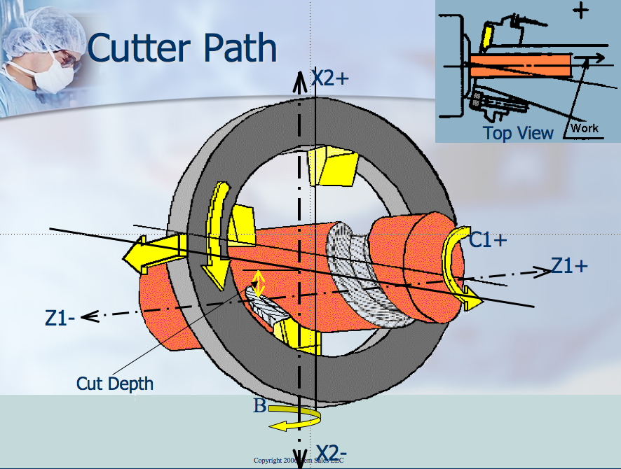
The cutting process is the result of a thread whirling cutter rotating at high speed around a slowly rotating workpiece in the “C-axis”. The rotation of the workpiece is combined with the advancement of the “Z-axis” head, which corresponds to the required pitch (see Fig. 1)
The cutting angle of the head is controlled around the “A-axis” to correspond to the pitch angle of the thread. The eccentricity of the “X-axis” determines the diameter of the thread. By simply changing the direction of travel of the “Z-axis”, it is possible to machine right-hand or left-hand threads. In each case, however, the rotary milling ring always rotates in the same direction as the workpiece, and it is this direction of travel that produces the desired left- or right-hand thread.
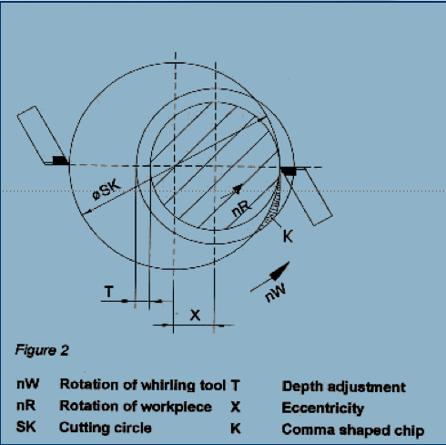
The thread whirling tool is mounted in the ring and moves relative to the workpiece. Ideally, this cutting process produces a comma-shaped chip (see Figure 2). Although rotary milling is an interrupted cutting process, the chip formation is so smooth that hardened and brittle materials up to 65 HRC can be cut with carbide, CBN (cubic boron nitride) or ceramic tools.
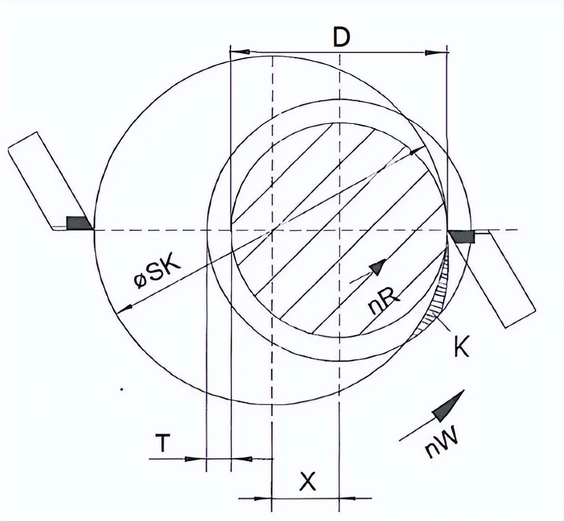
Thread whirling parameters:
- nW – Thread whirling cutter rotation
- nR – Workpiece rotation
- SK – Cutting circle.
- T – Depth adjustment (thread height)
- D – Tooth root diameter
- X – Eccentricity
- K – comma-shaped chip
Thread whirling vs Milling
When cutting external threads, we must first understand the similarities between thread whirling and milling. A thread whirling cutter ring has multiple cutting teeth, similar to a milling cutter. Each cutting edge removes a certain amount of material during a discontinuous cutting operation, but that’s about it for the similarities.
Due to the gradual entry and exit of the insert’s cutting edge, thread whirling has a more favourable cutting action, which permits higher metal removal rates. This smooth cutting action reduces radial pressure, which in turn reduces stress on the workpiece and the insert. In addition, tool life is significantly longer, making the process more cost-effective.
Features of thread whirling machine machining
Thread whirling is well known for the machining of long ballscrews (up to 10,000 mm in length and with tip diameters of 4-200 mm), especially in the medical industry for the production of bone screws.
However, this process has not yet been popularised by companies producing worm gears.
It is often defined as a non-traditional method of gear machining.
It is sometimes referred to as “planetary milling”, even though this term can be applied to another type of thread milling, where the tool rotates around its axis and revolves around a stationary workpiece to machine internal or external threads.

Workpiece blanks rotate at speeds of 3 to 30 rpm and whirling rings typically rotate at speeds of 1,000-3,000 rpm up to 10,000 rpm. Machining times are typically three to four times shorter than conventional milling, and up to nine times shorter for long screws.
For right-hand and left-hand spirals, the tool clamp ring and the blank always rotate in the same direction. Therefore, to form a worm with an opposite helix, the feed direction must be reversed and the inclination of the ring to the blank axis must be reversed.
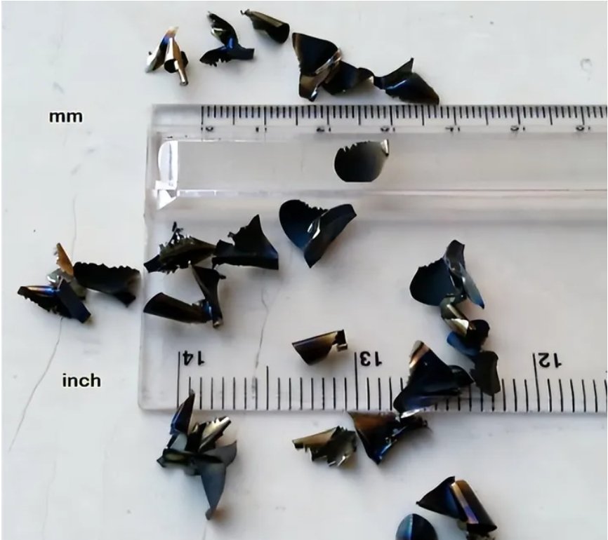
The thread whirling process is a discontinuous cut that produces comma shaped chips just like the standard milling process.
Considering the same worm geometry and the same angular advance (same angular speed), the swarf produced by rotary milling or milling has exactly the same volume, but in the rotary milling process the swarf is longer and thinner. This means that the rotary cutting process requires less cutting force and therefore less elastic deformation, resulting in better surface quality.
On the other hand, for the same chip size, thread whirling process requires less cutting time than milling because of higher cutting speed and feed. To sum up: the rotary cutting process has better metal removal rate.
Due to the shape of the chip, the heat generated during the cutting process dissipates into the chip itself, eliminating the need for coolant or cutting oil. This is another benefit: dry machining. Due to the high temperatures, the chips are blue in colour. Even at the end of the machining process, the workpiece remains cold. The tool can be coated with titanium aluminium nitride: Ti prevents the chips from sticking to the tool, and Al removes the heat quickly.
Surface quality of Thread whirling machining
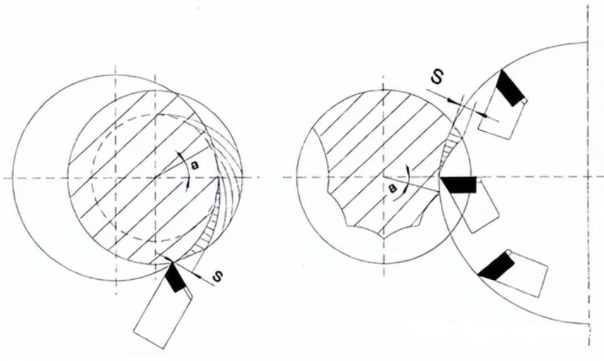
Thread whirling shapes are not perfect circles, but polygons, as in milling (and circles in turning). However, the maximum distance between these polygonal points and the outer circle is very small, about 0.1 µm in cyclone cutting, much smaller than in conventional milling. As a result, there will be better accuracy for the same cutting parameters, or possibly shorter cutting times for the same required accuracy.
Thread whirling chip generation: “s” is the chip size, “a” is the feed angle.
The surface roughness during milling of the worm is greater than during thread whirling, because in the latter case the insert enters the workpiece gradually. Milling with a large disc milling cutter (and therefore the same amount of chips in both processes) is faster, but the surface is rougher when milling because the cutter tries to climb the workpiece. As far as roughness is concerned, the comparison between worm-thread whirling and milling is very similar to the comparison between circumferential counter milling (conventional milling) and smooth milling (par milling).
It is well documented that surface roughnesses of Ra 0.5-0.6 µm and even Ra 0.4 µm can be achieved.
The accuracy of ballscrews machined by the rotary milling process can reach the accuracy of 3 DIN 6905 or ISO 3408-3, but it is not necessary to achieve such a good quality for industrial worm gearboxes, DIN 3974.
The thread whirling process has been successfully used on hardened steel instead of turning or grinding to reduce cycle times.
Comparing thread whirling with other methods of thread machining
| Method | Advantages | Disadvantages | Typical Applications |
| Thread Whirling | Extremely fast production* * High accuracy and surface finish* * Can produce deep threads and custom profiles* * Suitable for a variety of materials* | Specialized, expensive equipment* * Requires precise setup and helix angle calculations* | Medical bone screws* * Implants* * Feed screws* * Worm gears* * Microcomponents* |
| Single-Point Threading | Versatile, standard on most lathes* * Good for custom threads and short runs* | Slower than thread whirling* * Prone to tool wear on hard materials* | General purpose threading* * Large threads* * Prototyping* |
| Thread Milling | Flexible for complex thread forms* * Can handle interrupted threads* | Slower than whirling, especially for long threads* * Might require multiple passes * | Non-standard external threads* * Internal threads in large workpieces* |
| Die Threading | Very fast for standard external threads* * Simple and inexpensive tooling* | Limited to standard thread forms* * Primarily for external threads* | Mass production of bolts, fasteners* |
| Tap Threading | Fast for standard internal threads* * Easy to use* | Limited to standard thread forms* * Tap breakage risk with blind holes or hard materials* | Mass production of nuts, pipe fittings* |
Thread rolling is an additional method for primarily external threads. It’s fast and strengthens the material but is restricted to certain profiles and ductile materials.
Costs, precision, and optimal applications will vary within each method due to specific tooling and machine capabilities.
FAQs about thread whirling
What are the advantages of thread whirling?
Speed: Dramatically faster production times compared to traditional thread cutting.
Accuracy: Produces highly precise threads with tight tolerances.
Customizability: Can create a wide variety of thread profiles, pitches, and sizes.
Versatility: Suitable for both external and internal threads on various materials.
What materials are suitable for thread whirling?
Ideal: Steels, stainless steels, aluminum, titanium, brass, and some plastics.
Possible (with consideration): Harder materials can be whirled but may increase tool wear and require modified process parameters.
What are the typical applications for thread whirling?
High-precision: Medical implants, bone screws, aerospace components.
Mass-Production: Automotive fasteners, hydraulic components, precision worms and lead screws.
Micro-threads: Small components used in electronics and optics.
Are there any limitations to thread whirling?
Equipment Cost: Specialized whirling machines and tooling represent a higher initial investment than standard lathes.
Complexity: Setup and calculations for helix angles can be more involved than basic threading.
What produce can be machined by thread whirling?
Medical Components:
Bone screws
Dental implants
Surgical instruments with threaded components
Prosthetic fittings
Aerospace and Automotive Fasteners:
High-precision bolts
Threaded shafts
Nuts with specialized thread profiles
Hydraulic fittings
Industrial Machinery:
Lead screws
Worm gears
Precision shafts with threaded sections
Components for fluid or gas systems
Micro-Components:
Tiny screws for electronics and optics
Miniature threaded fasteners
Threaded components for medical devices
Custom Thread Forms:
Buttress threads
Acme threads
Unique or non-standard thread profiles

nice